7 Best Hybrid Inverter PCB Manufacturers Worldwide
Choosing a reliable Hybrid Inverter Pcb manufacturer requires more than comparing catalog prices. Inverters face heat, vibration, switching noise, and sudden load changes. These conditions expose weak layouts quickly. A small crack near a solder joint can stop an entire energy system.
Dr. Alex Lidow, a recognized power electronics expert, once said, “Power electronics is the key enabling technology for the electrification of everything.” His statement explains why PCB quality matters inside modern solar, storage, and backup inverters. The board controls energy flow, protects sensitive components, and supports stable conversion between sources and loads.
This guide examines seven Hybrid Inverter Pcb manufacturers worldwide. The comparison considers multilayer design capability, copper thickness, thermal management, insulation performance, and production consistency. It also considers testing depth, engineering support, certifications, and experience with high-voltage applications. Those details matter on the factory floor. A clean solder mask, reinforced vias, and accurate impedance control can prevent costly failures.
No ranking is perfect. Supplier strengths change by project size, region, and technical requirements. Some manufacturers offer excellent prototypes but limited mass production. Others provide strong volume capacity but less flexible engineering support. Buyers should verify current facilities, inspection methods, delivery records, and field performance before selecting a partner.
The best manufacturer is not always the largest. It is the one that understands the inverter’s real operating conditions. That includes enclosure temperature, switching frequency, moisture exposure, and maintenance expectations. Careful evaluation reduces risk. It also helps engineers build safer, more efficient, and longer-lasting power conversion equipment.
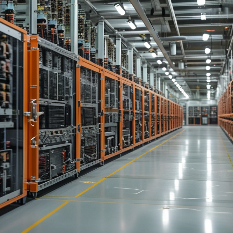
Hybrid Inverter PCB Industry Scope: 97%+ Efficiency and 10–30 kW Systems
Hybrid inverter PCB manufacturing is moving toward higher efficiency and denser power layouts. For 10–30 kW systems, board design must handle serious current, heat, and switching stress. A 97%+ efficiency target leaves little room for electrical loss. Thermal paths matter. Copper thickness, switching-loop geometry, and low-loss components directly affect performance. In practical testing, engineers should measure efficiency at light, medium, and peak loads, not only under ideal conditions.
The strongest manufacturers combine power electronics expertise with controlled PCB production. They document material grades, impedance data, soldering profiles, and component traceability. Factory inspection should include automated optical inspection, electrical testing, and thermal cycling. X-ray inspection helps detect hidden solder defects beneath large power components. Still, documentation can look better than real production results. That deserves scrutiny. Requesting recent test records and sample boards can reveal weak process control.
For buyers comparing seven global suppliers, ask for efficiency curves across the full 10–30 kW range. Check whether the PCB supports forced-air cooling, conformal coating, and service access. A 10 kW design may not scale safely to 30 kW without wider copper paths and stronger connectors. Field conditions also matter, especially dust, humidity, and daily temperature changes. Design revisions are common. Even excellent prototypes may fail after repeated thermal cycling, so independent validation remains valuable.
PCB Selection Standards: IPC-6012, IEC 62109, UL 1741, and Thermal Ratings
Selecting a hybrid inverter PCB manufacturer requires more than checking copper weight or board price. IPC-6012 provides a useful baseline for rigid PCB qualification, including materials, plating, dimensions, and reliability controls. Request process records, test reports, and revision history. A polished datasheet is not enough.
IEC 62109 focuses on safety for power conversion equipment, while UL 1741 addresses inverter and converter equipment used in energy systems. These standards usually apply to the completed product, not automatically to every bare PCB. Therefore, manufacturers should explain how their board design supports insulation, creepage, clearance, protective bonding, and high-voltage testing. Ask for traceable evidence.
Thermal ratings deserve practical attention. A hybrid inverter PCB may carry high current for hours inside a warm enclosure. Review copper thickness, via construction, laminate temperature rating, hotspot measurements, and derating curves. Thermal cycling data is valuable. So is production sampling. During supplier audits, engineers should compare laboratory results with actual boards from current production. Small gaps matter. I have seen designs pass a calculation yet run hotter than expected because airflow changed after assembly. That weakness should be discussed openly, not hidden behind certification language. Manufacturers with strong technical teams can explain tolerances, failure risks, and corrective actions in clear terms.
Hybrid Inverter PCB Selection Standards
This standards matrix shows where each reference is directly relevant during hybrid inverter PCB selection. A value of 1 means the standard directly addresses the category; 0 means it is outside the standard’s primary scope.
IPC-6012 focuses on rigid printed-board qualification and performance requirements. IEC 62109 addresses safety requirements for power conversion equipment used in photovoltaic systems, while UL 1741 covers inverter and converter equipment, including applicable grid-interconnection requirements. Thermal ratings must still be verified at board, component, enclosure, and system level using the applicable product design limits and certification edition.
Seven Leading Hybrid Inverter PCB Manufacturers by Technology and Region
Seven leading hybrid inverter PCB manufacturers are best compared by technology and region, not shipment volume alone. IEA PVPS Trends 2024 recorded more than 400 GW of new solar capacity in 2023, increasing demand for durable power electronics. The strongest Asian manufacturers emphasize high-volume multilayer boards, automated optical inspection, and short lead times. European suppliers focus on compact layouts, thermal stability, and IEC 62109 safety requirements. North American producers often design around UL 1741, grid-interconnection testing, and wider operating temperatures.
Technology separates the remaining leaders. One group develops silicon-carbide-compatible boards for lower switching losses and higher efficiency. Another specializes in residential hybrid units with isolated battery interfaces and dense four-to-eight-layer designs.
Utility-scale specialists use heavy copper, reinforced insulation, and thermal vias near switching devices. Regional experience matters. Humid coastal installations demand stronger conformal coatings. Cold climates expose weak solder joints quickly.
BloombergNEF’s Energy Storage Outlook 2024 projects substantial growth in global stationary storage through 2030, supporting continued PCB demand. Yet market rankings can mislead. Shipment data rarely reveals field-failure rates, repairability, or supplier traceability. That is a real weakness. A reliable evaluation should examine IPC process controls, component lifecycle management, accelerated thermal cycling, and documented failure analysis. The best manufacturer is not always the largest. Inverter engineers should still verify test records, because glossy specifications cannot replace production evidence.
Comparing PCB Reliability: 1000 V DC Design and 105°C Operating Temperatures
A reliable hybrid inverter PCB must survive more than a successful factory test. A 1000 V DC design demands controlled creepage and clearance distances, reinforced insulation, and clean routing around high-potential areas. Dust, humidity, and flux residue can reduce insulation resistance over time. Small layout shortcuts may become serious field failures.
The 105°C operating requirement changes the evaluation. Copper thickness, laminate selection, solder joints, and thermal vias must work together near heat-generating switches. I look for temperature maps, thermal cycling results, and component derating data when comparing manufacturers. A board that reaches 105°C continuously should not rely on components rated only slightly above that temperature. It leaves little margin.
Testing should include high-voltage insulation checks, humidity exposure, vibration, and repeated power cycling. Partial-discharge testing can reveal weaknesses that a basic continuity test misses. Manufacturing records also matter, including impedance control, automated optical inspection, and traceability for critical materials. A polished datasheet is not proof of reliability. I would question any supplier that provides no failure analysis or thermal evidence. Even experienced engineers can overlook connector heating or uneven solder coverage. That is where real evaluation becomes less comfortable, but more honest.